ISDN Fundamentals
Physically, an ISDN line into your home or office usually consists of the unshielded twisted pair cable which would, in the absence of ISDN service, be used for regular analog telephone calls. Typically, numerous ISDN devices connect onto this single line through a device known as an NT1 provided by the user in North America and by the carrier most everywhere else.
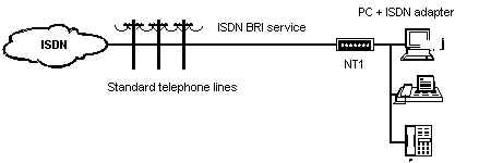
Logically, ISDN consists of two types of communications channels: bearer service B-channels, which carry data and services at 64 Kbps; and a single D-channel, which usually carries signaling and administrative information which is used to set up and tear down calls. The transmission speed of the D-channel depends on the type of ISDN service you've subscribed to.ISDN services available today can be divided into two categories: Basic Rate Interface (BRI) service, which gives the subscriber access to two B-channels and a 16 Kbps D-channel; and Primary Rate Interface (PRI) service, which provides access to 23 B-channels in North America and Japan and 30 B-channels in Europe most of Asia, and a 64 Kbps D-channel in both. These different types of services and channels are described in the sections that follow.
Basic
Rate Interface
ISDN BRI
is the most basic ISDN interface. ISDN BRI provides the customer with two
64 Kbps B-channels and one 16 Kbps D-channel, all of which may be shared
by numerous ISDN devices. It is the ideal service for homes and small offices
which, in the interest of controlling expenses, require a service that
can integrate multiple communications needs. By bundling the 2 B-channels
together and using 2:1 data compression, an ISDN BRI link can regularly
achieve data throughput of over 250 Kbps.Up to eight ISDN devices can be
connected on single bus, as signals on the D-channel automatically take
care of contention issues, and route calls and services to the appropriate
ISDN device. Although only two B-channels are available to be used at any
point in time, numerous other calls may be put "on hold" via D-channel
signaling (a feature referred to as multiple call appearances).
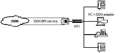
When more than one device is connected through a single ISDN BRI connection, individual devices are distinguished from one another through the use of multiple subscriber numbers, whereby a different ISDN number is assigned to each device served by the ISDN subscription. Alternatively, a separate subaddress value can be used to differentiate between devices.As described earlier, BRI functionality is attainable without any modification to the existing telephony infrastructure. Telephone companies must simply change the signaling on the local loop to support ISDN, but no physical modifications are required (although some local lines which are 15,000 feet or longer may require adjustment).
Primary
Rate Interface
ISDN PRI
includes one 64 Kbps D-channel and 23 B-channels in North America, and
30 B-channels in most other parts of the world. The number of B-channels
is limited by the size of the standard trunk line used in the region; T1
in North America and Japan and E1 most everywhere else. Unlike BRI, PRI
does not support a bus configuration, and only one device can be connected
to a PRI line. A PBX, however, can reallocate ISDN PRI resources onto multiple
BRI buses.

A single PRI connection is usually much less expensive than obtaining the equivalent number of B-channels through multiple BRI connections. Aside from its higher bandwidth, the primary benefit of PRI is that its bandwidth can be dynamically allocated among applications as required. For instance, certain channels can be allocated for voice calls, but as those calls are terminated, the unused B-channels can be reallocated to a high-bandwidth application such as a videoconference. This is usually accomplished via a PBX or powerful server which is capable of distributing the T1/E1 bandwidth on a PRI link.With its BRI and PRI services, ISDN has the flexibility to meet the needs of both individuals and corporations. Figure 8 demonstrates how BRI and PRI services can be used to meet bandwidth requirements of a home office, a branch office, or company headquarters.

In the upper left corner, a small office is using ISDN BRI to meet all of its various voice and data communications requirements, a common scenario when the expense of a PBX cannot be justified. In the lower left corner, multiple ISDN BRI lines are being divided among all of the applications within the office. This can be accomplished using a server or a PBX. The scenario shown on the right is usually found in large offices where the entire ISDN PRI bandwidth is filled by a variety of applications.
B-Channels
B-channels
are logical digital "pipes" which exist on a single ISDN line. For example,
if your ISDN subscription provides two B-channels, you could aggregate
the two to download data at very high speeds onto your PC. If you chose
to talk on your ISDN telephone, then one B-channel could be freed so that
only one B-channel would be used for data transfer and the other for your
conversation. B-channels each provide a 64 Kbps clear channel, clear
meaning that the entire bandwidth is available for data, since call setup
and other signaling is done through a separate D-channel.B-channels typically
form circuit-switched connections. Just like a regular telephone connection,
a B-channel connection is an end-to-end physical circuit that is temporarily
dedicated to transferring data between two devices. The circuit-switched
nature of B-channel connections, combined with their reliability and relatively
high bandwidth is what makes ISDN suitable for a range of applications
including voice, video, fax, and data. They can be used to transfer any
layer 2 or higher protocols across a link.Although B-channels are normally
used for on-demand connections, taking full-advantage of the circuit-switched
networks upon which they are based, they can also be configured as semi-permanent
or "nailed-up" connections which are always "up", much like a leased-line.

B-channels can also transfer packet-switched data such as X.25. X.31, for instance, is a specification which defines X.25 connections via an ISDN network. X.31 is not universally available from ISDN service providers, but when it is orderable, comes in one of two forms: Case A and Case B. X.31 Case A refers to ISDN connections into an X.25 packet-switched network external to the ISDN switch, while X.31 Case B defines X.25 connections that are set up directly from within a packet handler in an ISDN switch. Both are useful means of packet-switched X.25 communications, however service providers in Europe generally offer the former, and those in North America, the latter.
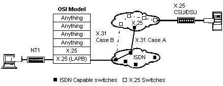
Recently, a number of service providers have launched similar services for ISDN access into Frame Relay networks. The main difference is that whereas X.25 presently supports switched virtual circuits, Frame Relay only supports permanent virtual circuits. Despite this present limitation, this technology is immmensely powerful, as the synergy between these two booming technologies enables inexpensive international communications, and inexpensive backup to Frame Relay access lines.
D-Channel
The D-channel
is used mostly for administrative signaling, such as instructing the ISDN
carrier to set up or tear down a call along a B-channel, to ensure that
a B-channel is available to receive an incoming call, or to provide the
signaling information that is required for such features as caller identification.
The D-channel uses packet-switched connections, which are best adapted
to the intermittent but latency-sensitive nature of signaling traffic,
thus accounting for the vastly reduced call setup time of 1 to 2 seconds
on ISDN calls (vs. 10 to 40 seconds using an analog modem). Depending on
ISDN service subscription, the D-channel transmits at either 16 Kbps (for
BRI service) or 64 Kbps (for PRI service).Unlike the B-channel, which can
function as a simple "pipe", the D-channel is associated with higher level
protocols at layers 2 and 3 of the OSI model which form the packet-switched
connections. The ITU layer 3 protocol specifications for use on the D-channel
is described within the DSS1 network layer definition. Q.931 is
the call-control protocol component of this definition, although various
carriers tend to use variants thereof. This layer 3 signaling protocol
is transferred on the D-channel using Link Access Procedure-D-channel (LAPD),
a layer 2 HDLC-like protocol.
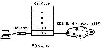
Although the layer 3 protocol takes care of most ISDN signaling requirements, LAPD, the layer 2 protocol, also plays a very important role in terms of low-level signaling to ISDN devices, which often share a single D-channel (in contrast to B-channels which are temporarily dedicated to specific ISDN devices). LAPD frames contain the information which ensures that incoming calls are routed to the appropriate ISDN device and pass the addressing information which distinguishes the numerous ISDN devices and services on a single line from each other. This is accomplished with the Terminal Endpoint Identifier (TEI) and Service Access Point Identifier (SAPI) fields within the LAPD frame.Despite the overall standardization of ISDN, numerous regional variants of Q.931 are used on the D-channel. As an ISDN user, you must ensure that your ISDN equipment supports the same D-channel protocol as your carrier.
| D-Channel Standards | |
| AT&T | 5ESS custom |
| Australia | TPH |
| CCITT | Q.931 |
| Europe | Euro-ISDN |
| France | VN3/4 |
| Germany | 1TR6 |
| Japan | NTT |
| N.A. | NI-1 |
| U.K. | NET3 |
D-Channel
Signaling and Carrier Networks
When the
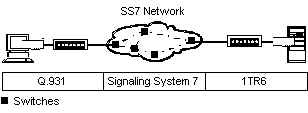
ISDN carrier receives a Q.931 instruction from a remote location, for example
to set up a call, it triggers network switches to set up an end-to-end
64 Kbps B-channel between the source and the destination directory number
signaled by Q.931. The carrier's network uses a different signaling system
though. Signaling between remote ISDN devices and the public voice and
data network switches occurs using D-channel protocols such as Q.931, which
in turn is converted into Signaling System No. 7 (SS7) signals within the
carrier's digital voice and data networks. With SS7, carriers are able
to maintain clear channel 64 Kbps connections by communicating signaling
information in a distinct channel. The switch at the destination side of
the network then communicates with the remote ISDN device using its D-channel
protocol (which in Germany, would be 1TR6).
Unfortunately, SS7 is not always fully implemented, leading to occasional limitations when ISDN connections traverse multiple switches. For instance, if one switch does not fully support SS7 ISDN features, call setup and signaling messages must be sent "in-band" or through the same communications channel as the bearer service. In other words, 8 Kbps of a 64 Kbps B-channel must be reserved for signaling, thus reducing available bandwidth. (This explains the 56 in "switched-56" services, which also use 8 Kbps of a 64 Kbps channel for signaling.)Any ISDN call that passes through at least one network which lacks full SS7 signaling, must therefore limit its B-channel traffic to 56 Kbps. In such cases the ISDN equipment on both ends must be configured to put only 56 Kbps of data onto their 64 Kbps link. In order to do so, the communications equipment at both ends must support a rate adaptation scheme which pads bandwidth above 56 Kbps with blank information, using such schemes as V.110 or V.120 rate adaptation. This feature is usually required whenever an an ISDN call originates in, is destined for, or passes through the United States, where 56 Kbps ISDN connections are not uncommon.

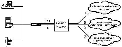
Although the D-channel is used primarily for packet-switched ISDN call signaling, it may also be used for packet-switched communications using alternative protocols such as X.25. This type of connection, which occurs via an ISDN switch's internal packet handler (X.31 Case B), is not available in all regions, however it is very useful for certain low-throughput applications such as credit card verification. In order to guarantee that ISDN services are unaffected by data traffic on the D-channel, ISDN signaling data is given a higher priority than any other traffic flowing through the D-channel.Figure 14 summarizes ISDN's switching flexibility, with its ability to support both packet-switched and circuit-switched services. Although the voice and data network, the SS7 signaling network, and the X.25 network are represented separately, all are intertwined, to the extent that they may be implemented within a single switch.
